RV’s need protection from potentially bad campground shore power and the Jeep we tow behind the motorhome needs to brake when the motorhome does.
ZAP Protection
Some campgrounds don’t have their shore power wired correctly. The vast majority of them do but if you run across the one that doesn’t it can zap your electronics on the RV. That can be very expensive. Not just DVD players but the inverter/charger that costs $1000. Other hardwired electronics like slide controllers, energy management systems, etc. also need protection. For a few hundred dollars I purchased a hardwired surge suppressor to safeguard all these systems. Since we have a 50 amp connection on the coach I selected the EMS-HW50C from Progressive Industries. From all the reviews I read this seems to be the best one out there. The suppressor comes with a remote display that continually shows the status of the incoming power and if any faults are detected it shows that too. The unit does more than just protect from a voltage spike, it also protects from under and over voltage and service that’s incorrectly wired. In all those cases it disconnects from the shore power automatically until proper service is restored. Installation is pretty straightforward. In my case the shore power enters the coach through a transfer switch. This box switches power between the campground hookup and the generator. In the picture below I have disconnected the shore power cable and I am installing a short jumper cable of 6 gauge wire to the transfer switch. This will connect to the output or load side of the surge suppressor. Needless to say, make sure you’re disconnected from shore power when you do this!
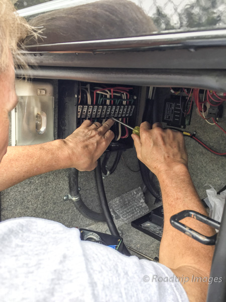
Just match the color codes, white wire to white, red to red and so forth. There are 4 wires in RV 50 amp service. At the surge suppressor box the other end of the jumper cable connects to the load side of the box. This side is a little tricky since you have to put current sensors on the red and black wires. There’s not a lot of room in the box for them and 6 gauge wire is pretty stiff. The wires get terminated in lug terminals and snugged down tight. This is shown in the photo on the left below. At the other end of the box is the long cable that gets plugged into the campground shore power. Those wires go into similar lug terminals. The green wires are ground wires and get ring terminals and then fastened to a ground buss on the side of the box. When all the wires are hooked up it looks like the photo below right. You can see the current sense coils on the red and black wires at the top of the box.


Once the wires are all connected the box can be sealed back up and then fastened to the wall of the compartment. Add some cable clamps to fasten the cables to the compartment as well. The remote display can be mounted pretty much anywhere. I put it near the front so the display is easier to read. The finished installation is shown below.
Toad Brakes – Part 1
The car you tow behind a motorhome is called a towed vehicle. Towed for short. The RV world has come to call these toads. No, I’m not making this up. Well, the toad needs to have it’s brakes come on whenever the motorhome applies it’s brakes. It’s actually law in most States. There are number of products out there to accomplish this and sorting through all of them took quite awhile. In one way or another they all “step” on the brake pedal in response to some sort of signal that the motorhome has hit the brakes. Some do it with inertia only, some with inertia plus the brake light signal from the coach, and some even tap into the air brakes on the coach to trigger the actuator in the car to hit the brakes. After looking at most of the products out there I zeroed in on the ones from SMI Mfg. I liked their approach to using a pneumatic cylinder mounted on the brake pedal. There’s nothing to remove from the car when you unhook the toad and want to turn it into a car again (no kissing of frogs required). I selected the Stay-In-Play Duo model as I didn’t want to tap into the air system on the coach which their Air Force One model required.


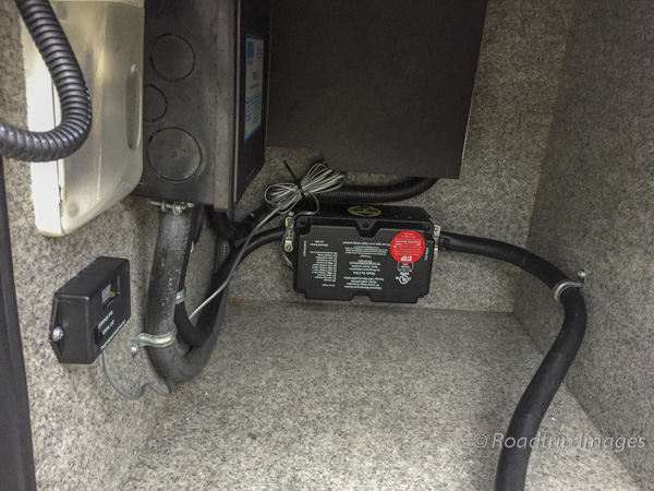
There are two main boxes that need to find a home in the car. On the left is the Operating unit and it houses the mini air compressor that provides air pressure to the pneumatic cylinder. SMI recommends placing this in the engine compartment and shows it wedged between the washer fluid reservoir and the master cylinder. Seems like a sketchy position but there isn’t a better one in our Jeep Wrangler. SMI recommends securing it with zip ties. Hmmm. The other location I’ve seen is underneath the drivers seat but that also has its share of difficulties. The second box is the control unit and it’s mounted on the drivers side under the dash. It’s shown below right. It contains the accelerometer that senses when the Jeep is decelerating. This combined with the brake signal from the motorhome tells the unit to apply the brakes in the car.


The pneumatic cylinder mounts to the brake pedal arm and then has a cable anchored back to the firewall. It’s shown below left. When the brakes need to be applied, the cylinder essentially pulls on the cable and pulls the brake pedal towards the firewall. It does this in proportion to how fast the Jeep is decelerating so if the motorhome is doing a gentle stop, so will the car. If it’s a panic stop then it will slam on the brakes in the car. This is important because you don’t want the car braking harder than the motorhome or pushing on it by not braking enough. It should brake at the same rate as the motorhome.
All the wires have to pass through the firewall to the engine compartment and fortunately most cars have a grommet installed just for this purpose. The cylinder also needs a small air hose and this goes through the same grommet. When installed it looks like below right.


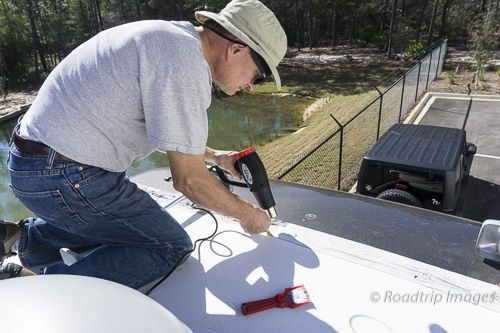
An LED light strip is attached to the back of the rear view mirror on the car to signal when the car brakes are being applied. This can be seen in the rear view camera mounted on the back of the coach and verifies that the system is working or if not, when to make any needed adjustments. For slow gentle braking the SMI system in the car shouldn’t even come on and the LED’s will let you know if that’s the case. The wires for these get tucked behind the trim along the windshield and down the side of the dashboard. A cover can be removed on the drivers side to gain access to pass the wires down to where the control unit is.


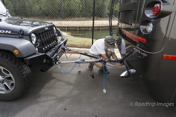
That’s it for this week. Next week in Part 2, I’ll finish up the install of the SMI brake system and we’ll hook up the Jeep to the motorhome with the new towbar system and take it for a spin. Till next time.